Search This Blog

Showing posts with label Inside PC. Show all posts

Monday, September 6, 2010

ASUS Xonar Essence STX


Audiophiles are interested in getting the best audio quality they can out of their components. The ASUS Xonar Essence STX is probably one of the best consumer level audio cards on the market thanks to its high signal-to-noise ratio, 192KHz/24bit support, superb digital to audio converters and even a built-in headphone amplifier. The audio components also have shielding to ensure that it doesn't receive any interference from other computer components. This provides it with some of the best playback and recording capabilities in a desktop audio card. The card does require an additional 4-pin power connector to provide it with sufficient power. It uses a PCI-Express x1 interface. Priced around $200.
 
 
ASUS Xonar Essence STX Virtual 7.1 Channels PCI Express Interface 124 dB SNR / Headphone AMP Card124DB Snr Headphone Amp 
 
Audio Chipset: ASUS AV100
Sample Rate: 192KHz
Digital Audio:24-bit
SNR: 118 dB Input Signal-to-Noise Ratio 124dB for Front-out 110dB for Headphone-out dB
Line In: Yes
SPDIF Out: High-bandwidth Coaxial/TOS-Link combo port supports 192KHz/24bit
MIC In: Yes
Other Ports: Aux-In (4-pin header on the card) Front-Panel Header: Shared by Headphone out / 2 channels out / Microphone in S/PDIF Header: Connects to compatiable graphic cards for HDMI output


Tuesday, August 24, 2010

Corsair Hydro Series of CPU Coolers


   The H70 model sports a double-thickness radiator in a space-saving profile.
Components-maker Corsair rolled out the latest iteration of its Hydro Series line of CPU coolers this week. An evolution of the H50 cooler, the new H70 model is designed to enable greater cooling performance.


    The new H70 CPU cooler sports two 120 mm, speed-switchable cooling fans in a push-pull configuration. It also features a double-thickness (50 mm) radiator with higher heat-exchanging capacity than its predecessors. Its pump/cold plate unit also boasts increased efficiency.
The Hydro Series is Corsair’s cooling line designed for CPUs from Intel and AMD.

    “Thanks to the H70, you no longer need a fin array the size of a small shoebox to cool aggressively overclocked CPUs,” says John Beekley, Corsair’s vice president of technical marketing.

    The Hydro Series H70 provides the benefits of water-cooling in a sealed and pre-filled unit. Its low-profile cold plate is designed for space efficiency and for less taxation of the motherboard.

   The H70 includes mounting hardware for most common AMD and Intel CPUs, and it includes all necessary fans.

Sunday, August 22, 2010

Kinds of Computer Motherboards

   Computer motherboards act as the backbone for every computing solution. The computer's motherboard is a common area for devices to interface and interact through disparate connection technologies and communications protocols. There are many ways for devices to connect and many technologies for them to communicate, and as such there are many different types of motherboards, each designed with specific computing duties in mind.

Form Factor

Form factors are design specifications that set guidelines for motherboard sizes, mounting screw locations and recommendations for connection socket locations on the motherboard itself. There are two classes of form factors that are of major concern. There is the ATX specification, which has several subclasses such as mini-ATX, ATX and Extended ATX. The ATX specification is used mainly for home computing solutions such as desktops and laptops. The second form factor of concern is the SSI specification, which has subclasses such as SSI CEB and SSI EEB. These motherboard specifications are designed for high-end enterprise solutions such as data servers, workstations and rack mount servers.

CPU Socket

The next consideration in differentiating a motherboard once a form factor has been determined is the CPU socket type. Every CPU has its own connective socket that is designed to accept a particular type or family of processors. Thus a motherboard is defined secondly by the processor type it is compatible with. Socket types are designed by their respective CPU companies. Enterprise-level motherboards often support dual, quad or even octal processor sockets.

Chip Set

A motherboard's intended use often dictates the chip sets it will have. Chip sets are controllers built into a motherboard that control such things as PCIe, SATA, EIDE and RAM communications. There are traditionally two chip sets on a motherboard, the north bridge and the south bridge. Their respective functions are varied by design and can often be designed to do the same tasks. The features of a motherboard's chip sets determine if and how well a motherboard will perform in a specific application.

Features

Motherboards can be designed to connect and communicate between a multitude of system devices. The current connective features on modern computer motherboards are designed to connect hard drives, add-on cards, CPU, system memory and peripheral device ports such as USB, Firewire and eSATA. Further, it is becoming more common for motherboard BIOS software to provide embedded tools for processor, RAM and chip set overclocking.

Considerations

When choosing a motherboard for a specific purpose, it is key to begin the selection process in a specific order to ensure your motherboard is compatible with the various devices on your computing solution. Form factor, CPU type, chip sets and finally connective sockets are the order in which you should begin the motherboard selection process. Narrowing your choices by any other order can lead to selecting a motherboard that is not compatible with your computing solution.
 

Typical Computer Motherboard

A typical PC mother board with important components is given below:


1. Mouse & keyboard
2. USB
3. Parallel port
4. CPU Chip
5. RAM slots
6. Floppy controller
7. IDE controller
8. PCI slot
9. ISA slot
10. CMOS Battery
11. AGP slot
12. CPU slot
13. Power supply plug in


1. Mouse & keyboard: Keyboard Connectors are two types basically. All PCs have a Key board port connected directly to the motherboard. The oldest, but still quite common type, is a special DIN, and most PCs until recently retained this style connector. The AT-style keyboard connector is quickly disappearing, being replaced by the smaller mini DIN PS/2-style keyboard connector.


You can use an AT-style keyboard with a PS/2-style socket (or the other way around) by using a converter. Although the AT connector is unique in PCs, the PS/2-style mini-DIN is also used in more modern PCs for the mouse. Fortunately , most PCs that use the mini-DIN for both the keyboard and mouse clearly mark each mini-DIN socket as to its correct use. Some keyboards have a USB connection, but these are fairly rare compared to the PS/2 connection keyboards.


2. USB (Universal serial bus):


USB is the General-purpose connection for PC. You can find USB versions of many different devices, such as mice, keyboards, scanners, cameras, and even printers. a USB connector's distinctive rectangular shape makes it easily recognizable.


USB has a number of features that makes it particularly popular on PCs. First, USB devices are hot swappable. You can insert or remove them without restarting your system.


3. Parallel port: Most printers use a special connector called a parallel port. Parallel port carry data on more than one wire, as opposed to the serial port, which uses only one wire. Parallel ports use a 25-pin female DB connector. Parallel ports are directly supported by the motherboard through a direct connection or through a dangle.

4. CPU Chip : The central processing unit, also called the microprocessor performs all the calculations that take place inside a pc. CPUs come in Variety of shapes and sizes.


Modern CPUs generate a lot of heat and thus require a cooling fan or heat sink. The cooling device (such as a cooling fan) is removable, although some CPU manufactures sell the CPU with a fan permanently attached.


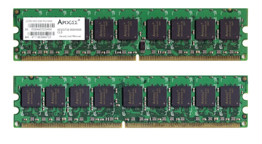
5. RAM slots: Random-Access Memory (RAM) stores programs and data currently being used by the CPU. RAM is measured in units called bytes. RAM has been packaged in many different ways. The most current package is called a 168-pin DIMM (Dual Inline Memory module).


6. Floppy controller: The floppy drive connects to the computer via a 34-pin ribbon cable, which in turn connects to the motherboard. A floppy controller is one that is used to control the floppy drive.

7. IDE controller: Industry standards define two common types of hard drives: EIDE and SCSI. Majority of the PCs use EIDE drives. SCSI drives show up in high end PCs such as network servers or graphical workstations. The EIDE drive connects to the hard drive via a 2-inch-wide, 40-pin ribbon cable, which in turn connects to the motherboard. IDE controller is responsible for controlling the hard drive.

8. PCI slot: Intel introduced the Peripheral component interconnect bus protocol. The PCI bus is used to connect I/O devices (such as NIC or RAID controllers) to the main logic of the computer. PCI bus has replaced the ISA bus.

9. ISA slot: (Industry Standard Architecture) It is the standard architecture of the Expansion bus. Motherboard may contain some slots to connect ISA compatible cards.


10. CMOS Battery: To provide CMOS with the power when the computer is turned off all motherboards comes with a battery. These batteries mount on the motherboard in one of three ways: the obsolete external battery, the most common onboard battery, and built-in battery.

11. AGP slot: If you have a modern motherboard, you will almost certainly notice a single connector that looks like a PCI slot, but is slightly shorter and usually brown. You also probably have a video card inserted into this slot. This is an Advanced Graphics Port (AGP) slot


12. CPU slot: To install the CPU, just slide it straight down into the slot. Special notches in the slot make it impossible to install them incorrectly. So remember if it does not go easily, it is probably not correct. Be sure to plug in the CPU fan's power.

13. Power supply plug in: The Power supply, as its name implies, provides the necessary electrical power to make the pc operate. the power supply takes standard 110-V AC power and converts into 12-Volt, 5-Volt, and 3.3-Volt DC power.


PhoenixBIOS Beep Code Troubleshooting

   PhoenixBIOS is a kind of BIOS manufactured by Phoenix Technologies. A majority of modern motherboard manufacturers have integrated Phoenix Technologies' PhoenixBIOS into their systems.

   Several custom implementations of the PhoenixBIOS system exist in many popular motherboards. The beep codes from a Phoenix-based BIOS may be exactly the same as the true Phoenix beep codes below or they may vary. You can always check your motherboard manual to be sure.


Note: PhoenixBIOS beep codes are short, sound in quick succession, and usually sound immediately after powering on the PC.

 
1 Beep

A single beep from a Phoenix based BIOS is actually an "all systems clear" notification. Technically, it's an indication that the Power On Self Test is complete. No troubleshooting necessary!
 
1 Long Beep, 2 Short Beeps

One long beep followed by two short beeps indicates that there has been a checksum error. This means that there is some kind of motherboard issue. Replacing the motherboard should fix this problem.

1-1-1-1 Beep Code Pattern

Technically, a 1-1-1-1 beep code pattern doesn't exist but I've seen it and many readers have too. Most often, it's a problem with the system memory. This Phoenix BIOS issue is usually corrected by replacing the RAM.

1-2-2-3 Beep Code Pattern

A 1-2-2-3 beep code pattern means that there has been a BIOS ROM checksum error. Literally, this would indicate an issue with the BIOS chip on the motherboard. Since replacing a BIOS chip is often not possible, this Phoenix BIOS issue is usually corrected by replacing the entire motherboard.

1-3-1-1 Beep Code Pattern

A 1-3-1-1 beep code pattern on a PhoenixBIOS system means that there has been an issue while testing the DRAM refresh. This could be a problem with the system memory, an expansion card, or the motherboard.

1-3-1-3 Beep Code Pattern

A 1-3-1-3 beep code pattern means that the 8742 keyboard controller test has failed. This usually means that there is a problem with the currently connected keyboard but it could also indicate a motherboard issue.

1-3-4-1 Beep Code Pattern

A 1-3-1-1 beep code pattern on a PhoenixBIOS system means that there is some kind of issue with the RAM. Replacing the system memory usually fixes this problem.

1-3-4-3 Beep Code Pattern

A 1-3-1-1 beep code pattern indicates some kind of issue with the memory. Replacing the RAM is the usual recommendation for solving this problem.

1-4-1-1 Beep Code Pattern

A 1-4-1-1 beep code pattern on a PhoenixBIOS system means that there is an issue with the system memory. Replacing the RAM usually fixes this problem.

2-1-2-3 Beep Code Pattern

A 2-1-2-3 beep code pattern means that there has been a BIOS ROM error, meaning an issue with the BIOS chip on the motherboard. This Phoenix BIOS issue is usually corrected by replacing the motherboard.

2-2-3-1 Beep Code Pattern

A 2-2-3-1 beep code pattern on a PhoenixBIOS system means that there has been an issue while testing hardware related to IRQs. This could be a hardware or misconfiguration problem with an expansion card or some kind of motherboard failure.

Other Phoenix Beep Codes

Many other PhoenixBIOS beep codes exist but are very uncommon. If you happen to come across a Phoenix beep code that I don't have listed above, let me know and I'll add the beep code and associated troubleshooting information to the list above.

AwardBIOS Beep Code Troubleshooting

   AwardBIOS is a kind of BIOS manufactured by Award, now owned by Phoenix Technologies. Many popular motherboard manufacturers use Award's AwardBIOS in their systems.

  Other motherboard manufacturers have created custom BIOS software based on the AwardBIOS system. The beep codes from an AwardBIOS-based BIOS may be the same as the original AwardBIOS beep codes (below) or they may vary a little. You can always reference your motherboard's manual if you to be sure.


Note: AwardBIOS beep codes sound in quick succession and usually immediately after powering on the PC.

 
1 Short Beep

A single, short beep from an Award based BIOS is actually an "all systems clear" notification. In other words, this is a beep code you want to hear and that you've probably been hearing each time your computer comes on since the day you purchased it. No troubleshooting necessary!
 
1 Long Beep, 2 Short Beeps

One long beep followed by two short beeps indicates that there has been some kind of error with the video card. Replacing the video card is usually the most you'll have to do to fix this one.

1 Long Beep, 3 Short Beeps

One long beep followed by three short beeps means that either the video card isn't installed or the memory on the video card is bad. Reseating or replacing the video card will typically fix the cause of this Award beep code.

1 High Pitched Beep, 1 Low Pitched Beep (Repeating)

A repeating high pitched / low pitched beep pattern is an indication of some kind of CPU problem. The CPU could be overheating or malfunctioning in some other way.

1 High Pitched Beep (Repeating)

A single, repeating, high pitched beeping sound means that the CPU is overheating. You'll need to figure out why the CPU is getting too hot before this Award beep code will go away.


Important: Turn your computer off immediately if you hear this beep code. The longer your CPU is running hot, the higher the chance that you'll permanently damage this expensive part of your system.

All Other Beep Codes

Any other beep code pattern you hear means that there has been some kind of memory problem. Replacing your RAM is the most you'll need to do to fix this problem.

AMIBIOS Beep Code Troubleshooting

  AMIBIOS is a kind of BIOS manufactured by American Megatrends (AMI). Many popular motherboard manufacturers have integrated AMI's AMIBOS into their systems.

   Other motherboard manufacturers have created custom BIOS software based on the AMIBIOS system. The beep codes from an AMIBIOS-based BIOS may be exactly the same as the true AMIBIOS beep codes below or they may vary slightly. You can always reference your motherboard's manual if you think this might be an issue.


Note: AMIBIOS beep codes are short, sound in quick succession, and usually sound immediately after powering on the PC.


1 Beep

A single beep from an AMI based BIOS means there has been a memory refresh timer error. The solution is often to replace the RAM in the computer.
 
2 Beeps

Two beeps means there has been a parity error in base memory. This is an issue with the first 64KB block of memory in your RAM. The solution is usually to replace the memory.

3 Beeps

Three beeps means there has been a base memory read/write test error. Replacing the RAM usually solves this AMI beep code.

4 Beeps

Four beeps means that the motherboard timer is not working properly. A hardware failure with an expansion card or the motherboard itself could be the cause of this beep code.

5 Beeps

Five beeps means there has been a processor error. A damaged expansion card, the CPU, or the motherboard could be prompting this AMI beep code.

6 Beeps

Six beeps means that there has been an 8042 Gate A20 test error. This beep code is usually caused by an expansion card that has failed or the motherboard that is no longer working.

7 Beeps

Seven beeps indicates a general exception error. This AMI beep code could be caused by an expansion card problem, a motherboard hardware issue, or a damaged CPU. Replacing the faulty hardware usually fixes the cause of this beep code.

8 Beeps

Eight beeps means that there has been an error with the display memory. This beep code is usually caused by a faulty video card. Replacing the video card usually clears this up.

9 Beeps

Nine beeps means that there has been an AMIBIOS ROM checksum error. Literally, this would indicate an issue with the BIOS chip on the motherboard. However, since replacing a BIOS chip is sometimes impossible, this AMI BIOS issue is usually corrected by replacing the motherboard.

10 Beeps

Ten beeps means that there has been a CMOS shutdown register read/write error. This beep code is usually caused by a hardware issue with the AMI BIOS chip. A motherboard replacement will usually solve this problem, although it could be caused by a damaged expansion card in rare situations.

11 Beeps

Eleven beeps means that the cache memory test has failed. Some piece of failing hardware is usually to blame for this AMI BIOS beep code.

What is BIOS?

The Basic Input Output System, abbreviated as BIOS, is software stored on a small memory chip on the motherboard.


BIOS is sometimes incorrectly referred to as the Basic Integrated Operating System.


What is the BIOS Used For?:


   BIOS instructs the computer on how to perform a number of basic functions such as booting and keyboard control.

   BIOS is also used to identify and configure the hardware in a computer such as the hard drive, floppy drive, optical drive, CPU, memory, etc.


How is BIOS Accessed?:


   The BIOS is accessed and configured through the BIOS Setup Utility. The BIOS Setup Utility is, for all reasonable purposes, the BIOS itself. All available options in BIOS are configurable via the BIOS Setup Utility.


How is BIOS Used?:

   BIOS contains a number of hardware configuration options that can be changed through the setup utility. Saving these changes and restarting the computer applies the changes to the BIOS and alters the way BIOS instructs the hardware to function.


BIOS Availability:


All modern computer motherboards contain BIOS software.

BIOS access and configuration on PC systems is independent of any operating system because the BIOS is part of the motherboard hardware. It doesn't matter if a PC is running Windows XP, Windows Vista, Linux, Unix, or no operating system at all - BIOS functions outside of the operating system environment and is no way dependent upon it.


BIOS manufacturer:


•AMI (AMIBIOS)


•Award (AwardBIOS)

•Phoenix (PhoenixBIOS)

PCI Express USB 3.0 card


     USB 3.0 is alive but many computers and motherboard still don’t have USB 3.0 supporting ports on them. If you’re on a desktop PC, there’s no need for you to purchase a brand new motherboard just so you can start benefiting from the latest USB, all that you need is one free PCI Express slot.


   USB 3.0 provides amazing speed and it is revolutionary with it, just as USB 2.0 when it was released. So if you want to enjoy USB 3.0 on your current PC you’ll just have to purchase Transcend`s USB 3.0 Expansion Card PDU3 and experience full power of it. This small card goes to your PCI Express slot and provides you two USB 3.0 ports on the back of your PC.

    Many people don’t even use this slot and all of the motherboards have it at the moment. Installing this card is rather easy, because it’s fully compatible with Windows 7 and all that you have to do is to place it into your PCI Express slot and you’re ready to experience the amazing transfer speed of the latest generation of USB. Speed of the USB 3.0 is ten times faster than the old 2.0, but at the moment there aren’t many devices that require USB 3.0 ports.

   Also this card provides backward compatibility and it is fully compatible with USB 2.0 and USB 1.1 and it provides a great solution if you have any device that uses USB 3.0. Since USB 3.0 is still away as a standard this card could be a great as a temporary solution for all the users who want to experience the speed of USB 3.0.


Latest Motherboard Technologies


ATX 12V 2.0:

ATX 12V is a new type of compliant to power supplies that feature a 24-pin 
connection that jack into new motherboards which have PCI-E capabilities. PCI-
E graphic cards can consume up to 75W of power compared to the 50W maximum 
limit on AGP cards. Most motherboards don't force you to buy a new PSU to run 
your 24-pin motherboard. They allow the older 20 pin connectors to work by 
leaving 4 pins vacant.


BTX Formfactor:

BTX is a new motherboard formfactor that moves the processor to the front of 
the case, moves the chipset in order to obtain higher I/O speeds and features 
better cooling. The BTX formfactor may have been greated very well by PC 
enthusiasts but the chasis manufacturers are not too happy since they have to 
shell out the big ucks, near $50K, to retool their assembly line. AMD is not 
following INTEL's footsteps since it stated to the public that it will not 
embrace this new standard unless customers ask for it. BTX has a way better 
design than its preceder, ATX, and it willdefenetively become the new standard 
soon.My guess is around 2-3 years.


DDR2 RAM:

The introduction of DDR2 has been really slow. DDR2 has improved apon DDR by 
by prefetching double the amount of data as DDR and it is designed to flo more 
than double the bandwith of DDR 3700 (400MHz). DDR2 sticks are not compatible 
with DDR at all sinceit electrically takes more power since it uses 1.8V while 
DDR used 2.5V and DDR2 is not physically fit to work dince it has 240 pins 
while DDR had 184 pins. DDR2 has not been proven to be worth it at its current 
400 and 533MHz speeds because of the increased latencies but DDR2 is comming 
out with 667  and 800MHz speeds which will be attractive.


Dual-Core CPU Support:

Two Processors will be featured on single CPU dies which will increase the 
performance for gammers but will probably have near no effect for non-gaming 
applications. Most applications will not be featuring/supporting this new 
feature any time soon but it is claimed that the users will have a "smoother" 
experience.AMD claims that all Socket 939 mobos that can run an FX-55 CPU will 
have no problem to take on the dual-core processors. On INTEL's side things 
are alot more confusing since their only dual core compatible chipset is the 
945/955X. Certain vendors say that 925X chipsets workfine as well. It is 
suggested that if you are shopping or a new motherboard make sure that it is 
dual-core compatible.


High-Definition Audio:
 
   High Definition Audio, also known as HD Audio or by its codename, Azalia, is an audio standard created by Intel to be used on their chipsets, i.e., it is a standard for high-quality on-board audio. In this tutorial we will explain more about this feature.
All Intel chipsets based on PCI Express bus – like i915 and i925 – support High Definition Audio. This standard provides two new features: multi-streaming, which allows more than one audio signal to be sent to a different audio device – for example, to watch a DVD on your living room transferring the audio thru a wireless network while talking thru a voice over IP solution at the same time on your desktop in your office – and high quality audio.
Before HD Audio was released, on-board high quality audio was only available if your motherboard had a separated high quality audio controller – like Envy24 from VIA, for example. With HD Audio technology, the south bridge of the chipset produces high-quality audio itself, without the need of a separated controller chip, what would make the motherboard more expensive. The south bridge only needs an external codec (coder/decoder) chip to make the needed digital/analog and analog/digital conversions. This kind of chip is inexpensive compared to a “full” controller chip. One example of codec compatible with Intel’s HD Audio is C-Media 9880.
High Definition Audio provides 7.1 surround audio with 192 KHz sampling rate and up to 32-bit resolution. Other audio solutions embedded on the chipset support a maximum of 48 KHz sampling rate and 20-bit resolution, even when they support 5.1 configuration (“6-channel surround audio”).


NCQ and SATA 3GB:
  
SATA 3GB is a pretty simple subject to graspsince the original SATA connection 
is now doubled to 300MB/s. Today's hard drives are not in need of such high 
speeds but there is no reason why no to have it tho if you buy a new mobo. NCQ 
or nativecommand queuing is very important since it enables your hard drive 
and its controller to reorder data requests according to priority in an 
intelligent manner. This extra hard drive intelligence allows it to collect 
and write data faster than before. Even tho NCQ only gives small performance 
boosts according to the ressources that I used, it is still worth having when 
buying a new mobo.


PCI-Express:

PCI-Express has become the new motherboard standard practically overnight 
since the change happened so fast. PCI-E has proven to be faster than the 
older AGP standard but there isn't a big performance boost unless two PCI-E 
cards are paired together. PCI-E is one of the few leaders so far that have 
moved away from wide and slow interfaces with lots of pins to narrow and high-
speed interfaces. AGP's bandwith was 2GB/s but now PCI-E has brought the 
bandwith up to a great 8GB/s. PCI-E also has the greatest advantage in its 
upstream bandwith since AGP had a 133MB/s bandwith but now PCI-E has a 
bandwith of 4GB/s which is a tramendous improvement. The new x1 PCI-E 
connector is going to try to take over PCI slots since it offers 300MB/s which 
is more than double of PCI's bandwith. On todays motherboards there are 
already so many integrated parts that the more and more expansion slots are 
being left empty. However, software developpers will be soon taking advantage 
of this in the near future to my predictions.


SLI:

Sli which is also known as scalable link interface is the process of running 
to video cards together to generate an image onto one screen. SLI allows two 
GPUs, graphic processing units, to share the work load while displaying their 
content on a single monitor. To do this it requires a motherboard that has two 
x16 PCI-E slots. When buying orsetting up this configuration must customers do 
not realise that they are not going to get x16 bandwith ineach slot. Current 
boards top out at around x20. There are two possible configurations. It is 
possible to set them up so that one runs at x16 and the other at x4 or you can 
make them both run at x8 which is said to be the optimal setting. On most 
current SLI mobos a switch or pin must be turned on to enable or disable SLI 
mode. There is a catch for SLI at the current stage of the game. If you play 
current games a big performance boost wont be seen but in the near future 
those twins will become veryusefull since future games are likely to run 
faster technology.


A Computer BUS (PCI-Express Compared)


   The processor communicates with other peripherals in the PC through a path of data called bus. Since the release of the first PC, in 1981, up to the present day, several types of bus have been developed in order to allow the communication between the processor and input and output peripherals. We can name the following buses already launched:
  • ISA
  • EISA
  • MCA
  • VLB
  • PCI
  • AGP
  • PCI Express
 
    The main difference among the several types of bus is in the number of bits that can be transmitted at a time, and in the operating frequency used. Nowadays the two fastest types of PC expansion bus are the PCI and the AGP. We listed the transfer rate of those buses in the chart below. The PCI-X bus is an extension of the PCI bus designed to the market of network servers
Bus
Clock
Number of bits
Data per Clock Cycle
Maximum Transfer Rate
PCI
33 MHz
32
1
133 MB/s
PCI
66 MHz
32
1
266 MB/s
PCI
33 MHz
64
1
266 MB/s
PCI
66 MHz
64
1
533 MB/s
PCI-X 64
66 MHz
64
1
533 MB/s
PCI-X 133
133 MHz
64
1
1,066 MB/s
PCI-X 266
133 MHz
64
2
2,132 MB/s
PCI-X 533
133 MHz
64
4
4,266 MB/s
AGP x1
66 MHz
32
1
266 MB/s
AGP x2
66 MHz
32
2
533 MB/s
AGP x4
66 MHz
32
4
1,066 MB/s
AGP x8
66 MHz
32
8
2,133 MB/s

   The PCI bus was released by Intel in June, 1992. Since then, almost all PC expansion peripherals, such as hard disks, sound cards, LAN cards, and video cards have been using the PCI bus. The thing is, the PCI bus maximum transfer rate - 133 MB/s – proved to be insufficient for modern 3D applications and it represented a limitation to the development of more sophisticated video cards. In order to solve that issue, Intel created a new bus, called AGP, to increase the transfer rate of video cards – now they wouldn’t have to be installed in the PCI bus anymore, but in the AGP bus, which is faster. Then the PCI was not so “busy” anymore, since video cards were the great responsible for the intense traffic in the PCI bus.
For more information on AGP bus, read our AGP Bus Tutorial.
With the coming of faster graphics chips and new network technologies, such as Gigabit Ethernet and RAID technology, once more the maximum transfer rate of the PCI bus proved to be insufficient to handle those new applications. Something needed to be done and the answer came with the launching of the PCI Express bus.
In the tutorial we will explain in details how the PCI Express bus works and how it differs from the PCI bus.

Obs: Technically speaking, PCI Express is not a bus. A bus is a data path where you can attach several devices at the same time, sharing this data path. PCI Express is a point-to-point connection, i.e., it connects only two devices and no other device can share this connection. Just to clarify, on a motherboard using standard PCI slots, all PCI slots are connected to the PCI bus and share the same data path. On a motherboard with PCI Express slots, each PCI Express slot is connected to the motherboard chipset using a dedicated lane, not sharing this lane (data path) with other PCI Express slots. In name of simplification, we are calling PCI Express as a "bus", since for laymen “bus” is easily recognized as “data path between devices”.


From Parallel to Serial
 
   The PCI Express bus (formerly known as 3GIO) represents an extraordinary advance in the way peripheral devices communicate with the computer. It differs from the PCI bus in many aspects, but the most important one is the way data is transferred. The PCI Express bus is an example of how PC data transfer is migrating from parallel communication to serial communication. Read our article Why Serial? to understand the differences between serial and parallel communications.

   Almost all PC buses (ISA, EISA, MCA, VLB, PCI and AGP) use parallel communication. Parallel communication differs from the serial one because it transmits several bits at a time, while in serial communication only one bit is transmitted at a time. This makes, at first, parallel communication faster than the serial one, since the higher the number of bits transmitted at a time, the faster the communication will be.

   But parallel communication suffers from some problems that prevent transmissions from reaching higher clocks. The higher the clock, the greater will be the problems with magnetic interference and propagation delay.

   When the electric current passes flows through a wire, an electromagnetic field is created around it. If the electromagnetic field created by the wire happens to be very strong, noise will be produced in the near wire, corrupting the information being transmitted. As in parallel transmission several bits are transmitted at a time, each bit involved in the transmission uses one wire. For example, in a 32-bit communication (such as the PCI slot) it’s necessary to have 32 wires just to transmit data, not counting additional control signals that are also necessary. The higher the clock, the greater the electromagnetic interference problem.

 
Operation Modes
 
   The PCI Express bus has been developed to substitute PCI and AGP buses. It’s compatible in terms of software to the PCI bus, which means old drivers and operating systems don’t need to go through changes in order to support the PCI Express bus.

   The PCI Express bus is a serial bus that works in full-duplex mode. Data is transmitted in this bus through two pairs of wires called lane, by using the codification system 8b/10b, the same system used in Fast Ethernet (100BaseT, 100 Mbps) networks. Each lane allows a maximum transfer rate of 250 MB/s in each direction, almost twice the rate of the PCI bus. The PCI Express bus can be built by combining several lanes in order to achieve higher performance. We can find PCI Express systems with 1, 2, 4, 8, 16 and 32 lanes. For example, the transfer rate of a PCI Express system with 8 lanes (x8) is 2 GB/s (250 * 8).

   On the chart below are the transfer rates of the PCI, AGP and PCI Express busses.
Bus
Maximum Transfer Rate
PCI
133 MB/s
AGP 2x
533 MB/s
AGP 4x
1,066 MB/s
AGP 8x
2,133 MB/s
PCI Express x1
250 MB/s
PCI Express x2
500 MB/s
PCI Express x4
1,000 MB/s
PCI Express x16
4,000 MB/s
PCI Express x32
8,000 MB/s
 
   The PCI Express bus is hot plug, i.e., it’s possible to install and remove PCI Express boards even when the PC is on.


Popular Posts